Specialized Torsion System for Rotating Beam Testing
How it Works
To perform a test with ADMET’s Rotating Beam Tester, a sample is placed in the machine and a force is applied via a bending moment from a secondary actuator. The force induces a surface stress that will be tensile on one side of the sample and compressive on the opposite side. When the test is started, the sample will rotate at the desired rate and this rotation will cause the surfaces to interchange so that each surface experiences alternating tensile and compressive stresses. The sample is left in the machine until failure at which point ADMET’s eP2 controller will display the number of cycles it took for the sample to fail. Running a series of tests on identical samples with varying stresses will allow the user to create an S-N curve.
Features
- Uses four-point beam loading condition to provide a consistent bending stress across the gauge section of the specimen
- eP2 Controller for system control and cycle counting
- Sample Break detection
- Safety shield with interlock switch
- Multiple collet sizes available depending on the specimen geometry
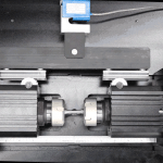
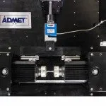
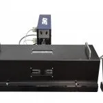
- eXpert 9300 Rotating Beam Fatigue – Safety cover off
- eXpert 9300 Rotating Beam Fatigue Machine – Sample failure
- eXpert 9300 Rotating Beam Fatigue – Pure bending moment actuator
- eXpert 9300 Rotating Beam Fatigue Machine – Preloading sample
- eXpert 9300 Rotating Beam Fatigue – Top down view
- eXpert 9300 Rotating Beam Fatigue – Safety cover on
Rotating beam fatigue testing systems were first developed in the mid-1800s by a German railroad engineer named August Wöhler. He designed the machine to test railroad car axles and investigate axle brake failures. The principles upon which that machine was developed still apply today.
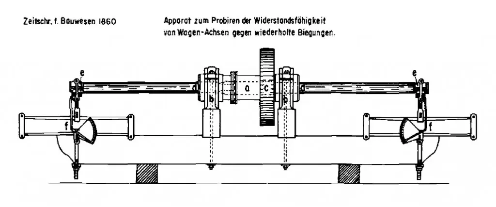
Wohler’s Fatigue Testing Machine
A spindle in the center of the machine is supported by two bearing blocks and rotated at approximately 15 rpm. Two axles were mounted to both ends of the rotating spindle and bending forces were applied to the axles thru a spring mechanism located at both ends of the machine.
Between 1852 and 1870, the first systematic fatigue tests were carried out on specifically designed laboratory specimens by Wöhler. These tests enabled Wöhler to relate his experimental results to the stresses in locomotive axles. In 1870, Wöhler compiled a report of his experimental work which contained several conclusions known as Wöhler’s laws:
- Materials can be induced to fail by many repetitions of stress, all of which are lower than the static strength.
- Stress amplitudes (or stress range) are decisive for the destruction of the cohesion of the material.
- The maximum stress is of influence only in so far as the higher it is, the lower are the stress amplitudes (or stress ranges) which lead to failure. This translates to increasing the mean stress decreases the number of cycles to failure.
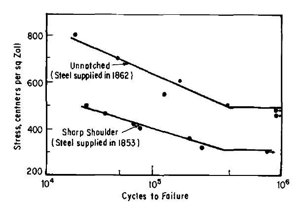
Wohler’s S-N curves for Krupp axle steel
Stress life testing is based on Wöhler’s work and requires multiple constant amplitude fatigue tests on identical samples to generate an S-N or Wöhler diagram.
Key Terms
Fatigue: Fatigue failure is a time dependent failure of a material or component due to a cyclic stress that is lower than the material’s Elastic Limit or Ultimate Tensile Strength. Fatigue is generally associated with tensile stresses but there are special circumstances when it can occur in compression.
Frequency: Frequency is a measure of the number of tension and compression cycles the sample goes through. This is typically measured in Hertz (Hz) which is the number of cycles the sample goes through per second. For metals, it is generally accepted that below 200 Hz, the fatigue behavior is independent of the frequency.
S-N Curve: An S-N curve, also known as a Wöhler curve, is a graph that shows a material’s fatigue behavior and endurance limit if it is distinct. As the stress applied to the sample decreases, the number of cycles to failure will increase. The graph shows the stress amplitude (S), the difference between the maximum and minimum stress during a fatigue cycle divided by 2, and the number of cycles (N). A logarithmic scale is typically used for the number of cycles. Depending on the material the graph may approach a limit which is known as the Endurance Limit (SL).
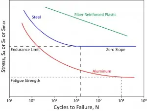
S-N Diagram for steel, fiber-reinforced plastic, and aluminum
Endurance Limit (SL): The endurance limit of a material is the maximum stress that can be applied to the material indefinitely without failure. Depending on the material, they may or may not show this behavior. Ferrous and titanium alloys typically have endurance limits along with polymers. Materials such as aluminum and copper do not and can fail at very low stresses. Cycling below the endurance limit can be done indefinitely without failure.
Cycle to Failure: Cycle to Failure is the number of cycles before a sample fails. The larger the stress, the less the number of cycles to failure will be. If the stress is below the materials Endurance Limit, theoretically the cycles to failure is indefinite.
Bending Moment: A bending moment is a force that causes a sample to bend. The bending moment is a function of the force applied, the distance from where the sample is supported to where the moment is acting, and the geometry of the sample.


